Journals > > Topics > Lasers and Laser Optics
Lasers and Laser Optics|1604 Article(s)

High-Efficiency Fiber Combining of Long-Wave Infrared Quantum Cascade Lasers
Meng Zhang, Xin Wang, Suhui Yang, Bao Li, Zhuo Li, Jinying Zhang, and Yanze Gao
ObjectiveQuantum cascade laser (QCL) is a semiconductor laser based on sub-band electronic transition, which results in a broad emitting wavelength covering from 3 to 300 μm. QCL is an ideal light source in the fields of gas sensing, environmental monitoring, medical diagnosis, and photoelectric countermeasures. However, the relatively low output power (1-3 W) of the single transverse mode QCL is a major limitation for its applications. Laser beam combining technology is an effective way to enhance the output power. At present, the power beam combining of mid-infrared and long-wave infrared QCLs is heavily limited by the low-loss optical materials and component preparations. Beam combining with high efficiency and low loss is challenging, and few research results have been reported. Therefore, the fiber combining of long-wave infrared QCLs in the 7.6-7.8 μm wavelength band was studied in this paper. The laser power was combined with a 4-in-1 single-mode hollow-core fiber bundle.MethodsIn order to realize the high-efficiency single-mode fiber coupling of QCLs, the optical fiber coupling system was designed. The optical fiber system was composed of a QCL collimator and a fiber coupler. Due to the large QCL emitting area and large divergence angle, an aspheric collimator with a large numerical aperture was designed and fabricated. During the optical design and optimization, the QCL was assumed to be an extended light source. Using the optimized collimator, a fiber coupling efficiency of 88.9% was obtained. To combine the laser beams from individual QCL, a 4-in-1 fiber combiner was fabricated using AgI/Ag single-mode hollow-core fiber, which had a high damage threshold and low transmission loss. During the preparation, the outer protective layer of the fiber was stripped away, and the four fibers were tightly arranged in the sleeve and fixed. Finally, the fiber was protected by metal armor. The input terminals of the fiber combiner were four independent SMA905 fiber connectors, and a unified SMA905 connector was made at the output end.Results and DiscussionsThe optical fiber coupling experiments are conducted using the designed optical fiber coupling system and the prepared long-wave single-mode hollow-core fiber combiner. When the QCL output power is 642 mW, the laser power throughout the single-mode fiber is 438 mW. The corresponding fiber coupling efficiency is 68%. In addition, we experimentally compare the coupling efficiency using a point-source collimator and an extended-source collimator. Using the extended-source collimator with a large numerical aperture, the fiber coupling efficiency is increased from 59% to 68%, as shown in Fig. 10. An infrared camera is used to observe the collimated QCL spot and the beam spot out of the single-mode fiber. In addition, the beam propagation quality factor M2 after the fiber coupling is calculated. After the fiber coupling, a symmetric Gaussian distribution is observed, and the beam quality is improved to 1.2, compared to the M2 in Table 7. On the basis of the single-channel optical fiber coupling experiment, the optical fiber combining experimental setup of a four-channel long-wave infrared QCL is built. When the total input power from four QCLs is 2.27 W, the fiber combining power is 1.5 W. The corresponding combining efficiency is 66%. In order to evaluate the beam quality of the combined beam, the lens is used to focus the output light, and the intensity distribution of the output spot of the beam combiner is measured within two times Rayleigh distance. The results are shown in Figs. 14 and 15. The transmission quality factors of the combined beam are calculated as MX2=2.67 and MY2=2.56, which meant a good beam quality.ConclusionsIn this paper, the long-wave infrared QCL beam combining technology based on single-mode hollow-core fiber is studied. Considering the large emitting area and big divergent angle of the fundamental transverse mode long-wave infrared QCL, a QCL collimator with a large numerical aperture is used. During the design, the QCL is treated as an extended light source. To obtain the optimized collimation result, both surfaces of the collimator are aspheric. A 4-in-1 fiber combiner is fabricated using the AgI/Ag single-mode hollow-core fiber. The fiber has no end face reflection loss and low transmission loss. The experimental results show that the single-mode fiber coupling efficiency is 68%. After the fiber coupling, the beam propagation quality factor M2 is 1.2. In addition, the power combining of four QCLs in the wavelength band of 7.6-7.8 μm is realized. When the input power is 2.27 W, the combined output power is 1.5 W. The beam combining efficiency is 66%. The transmission quality factors of the combined beams are MX2=2.67 and MY2=2.56. The low-loss working band of the fiber combiner ranges from 7 to 15.5 μm. The output optical power can be further increased by increasing the number of QCLs in the beam combining, which provides an effective way to expand the output power and wavelength range in the long-wave infrared wavelength band. ObjectiveQuantum cascade laser (QCL) is a semiconductor laser based on sub-band electronic transition, which results in a broad emitting wavelength covering from 3 to 300 μm. QCL is an ideal light source in the fields of gas sensing, environmental monitoring, medical diagnosis, and photoelectric countermeasures. However, the relatively low output power (1-3 W) of the single transverse mode QCL is a major limitation for its applications. Laser beam combining technology is an effective way to enhance the output power. At present, the power beam combining of mid-infrared and long-wave infrared QCLs is heavily limited by the low-loss optical materials and component preparations. Beam combining with high efficiency and low loss is challenging, and few research results have been reported. Therefore, the fiber combining of long-wave infrared QCLs in the 7.6-7.8 μm wavelength band was studied in this paper. The laser power was combined with a 4-in-1 single-mode hollow-core fiber bundle.MethodsIn order to realize the high-efficiency single-mode fiber coupling of QCLs, the optical fiber coupling system was designed. The optical fiber system was composed of a QCL collimator and a fiber coupler. Due to the large QCL emitting area and large divergence angle, an aspheric collimator with a large numerical aperture was designed and fabricated. During the optical design and optimization, the QCL was assumed to be an extended light source. Using the optimized collimator, a fiber coupling efficiency of 88.9% was obtained. To combine the laser beams from individual QCL, a 4-in-1 fiber combiner was fabricated using AgI/Ag single-mode hollow-core fiber, which had a high damage threshold and low transmission loss. During the preparation, the outer protective layer of the fiber was stripped away, and the four fibers were tightly arranged in the sleeve and fixed. Finally, the fiber was protected by metal armor. The input terminals of the fiber combiner were four independent SMA905 fiber connectors, and a unified SMA905 connector was made at the output end.Results and DiscussionsThe optical fiber coupling experiments are conducted using the designed optical fiber coupling system and the prepared long-wave single-mode hollow-core fiber combiner. When the QCL output power is 642 mW, the laser power throughout the single-mode fiber is 438 mW. The corresponding fiber coupling efficiency is 68%. In addition, we experimentally compare the coupling efficiency using a point-source collimator and an extended-source collimator. Using the extended-source collimator with a large numerical aperture, the fiber coupling efficiency is increased from 59% to 68%, as shown in Fig. 10. An infrared camera is used to observe the collimated QCL spot and the beam spot out of the single-mode fiber. In addition, the beam propagation quality factor M2 after the fiber coupling is calculated. After the fiber coupling, a symmetric Gaussian distribution is observed, and the beam quality is improved to 1.2, compared to the M2 in Table 7. On the basis of the single-channel optical fiber coupling experiment, the optical fiber combining experimental setup of a four-channel long-wave infrared QCL is built. When the total input power from four QCLs is 2.27 W, the fiber combining power is 1.5 W. The corresponding combining efficiency is 66%. In order to evaluate the beam quality of the combined beam, the lens is used to focus the output light, and the intensity distribution of the output spot of the beam combiner is measured within two times Rayleigh distance. The results are shown in Figs. 14 and 15. The transmission quality factors of the combined beam are calculated as MX2=2.67 and MY2=2.56, which meant a good beam quality.ConclusionsIn this paper, the long-wave infrared QCL beam combining technology based on single-mode hollow-core fiber is studied. Considering the large emitting area and big divergent angle of the fundamental transverse mode long-wave infrared QCL, a QCL collimator with a large numerical aperture is used. During the design, the QCL is treated as an extended light source. To obtain the optimized collimation result, both surfaces of the collimator are aspheric. A 4-in-1 fiber combiner is fabricated using the AgI/Ag single-mode hollow-core fiber. The fiber has no end face reflection loss and low transmission loss. The experimental results show that the single-mode fiber coupling efficiency is 68%. After the fiber coupling, the beam propagation quality factor M2 is 1.2. In addition, the power combining of four QCLs in the wavelength band of 7.6-7.8 μm is realized. When the input power is 2.27 W, the combined output power is 1.5 W. The beam combining efficiency is 66%. The transmission quality factors of the combined beams are MX2=2.67 and MY2=2.56. The low-loss working band of the fiber combiner ranges from 7 to 15.5 μm. The output optical power can be further increased by increasing the number of QCLs in the beam combining, which provides an effective way to expand the output power and wavelength range in the long-wave infrared wavelength band.
Acta Optica Sinica
- Publication Date: Apr. 25, 2024
- Vol. 44, Issue 8, 0814003 (2024)

976 nm Fundamental Transverse Mode Ridge Diode Laser with Narrow Far-Field Divergence Angle
Zhennuo Wang, Li Zhong, Deshuai Zhang, Suping Liu, Zhipeng Pan, Jinyuan Chang, Tianjiang He, and Xiaoyu Ma
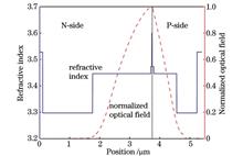
ObjectiveAs the main pumping light source of solid state laser, fiber laser, and fiber amplifier, 976 nm diode laser has been widely used in industrial processing, medical treatment, communication, and other fields. As an important pumping light source of erbium-doped fiber amplifier, a 976 nm fundamental transverse mode diode laser can achieve high-efficiency coupling with fiber, improve the output performance of the fiber amplifier, and effectively reduce the cost of the fiber amplifier. It plays a very important role in improving the application of erbium-doped fiber amplifier in fiber communication and other fields. However, since the ridge waveguide in the ridge diode laser uses the weak refractive index guiding mechanism to suppress the higher-order transverse mode, it will be greatly affected by the lateral diffusion of carriers and the self-heating effect and eventually lead to the decline of the ridge waveguide mode guiding and the increase of the far-field angle. To further improve the coupling efficiency of diode lasers in fiber laser pumping applications and reduce the application cost of fiber lasers, it is still important to realize low far-field divergence angle and low power consumption of fundamental transverse mode ridge diode lasers.MethodsUsing InGaAs/GaAsP material as the strain-compensated quantum well structure, and GaAsP with high bandgap width as the barrier material can effectively reduce the carrier leakage effect of quantum well, provide strain compensation for InGaAs compressive strain quantum well, and improve the epitaxial growth quality. To achieve low loss, we optimize high output optical power and low far-field angle, the thickness of waveguide layers by using asymmetric large optical cavity epitaxial structure. The doping concentrations of the epitaxial layer materials are optimized to reduce the series resistance of the device, to achieve high power, high conversion efficiency, and low far-field output of the ridge diode laser. To achieve fundamental transverse mode output, we use the effective refractive index method to design and study the width and depth of the ridge waveguide and map the optical field distribution inside the device. Finally, according to the technological conditions, the ridge waveguide structure is selected with a width of 5 μm and a depth of 0.85 μm.Results and DiscussionsAfter the laser chip is designed and prepared, the output performance of the device is tested at 25 ℃. The device threshold current is about 51.2 mA, and a maximum continuous output power of 422 mW can be obtained at 550 mA injection current, with a maximum electro-optic conversion efficiency of 53.6% (Fig. 3). The peak wavelength is 973.3 nm at 550 mA injection current, and the corresponding spectral line width (FWHM) is 1.4 nm. When the injection current is 500 mA, the vertical and horizontal far-field distribution diagrams of the device are drawn (Fig. 5), and the corresponding vertical and horizontal far-field divergence angles (FWHM) are 24.15° and 3.9°, respectively. This indicates that the prepared ridge diode laser has a good fundamental transverse model property, which is conducive to improving the coupling efficiency between the diode laser and the fiber. Subsequently, we analyze the temperature characteristics of the device at the operating temperature of 15-35 ℃ and obtain a relatively high characteristic temperature of about 194 K. This is because GaAsP material with high band gap width is added to both sides of the InGaAs quantum well as the barrier layers, and there is a larger band level between the two materials, which can better suppress carrier leakage in the quantum well. The injection current utilization, the luminous efficiency, and the temperature stability of the laser device are improved. Similarly, the horizontal far-field changes little at 15 ℃, 25 ℃, and 35 ℃, and the corresponding horizontal far-field divergence angles are 3.45°, 3.90°, and 3.90°, respectively, which is conducive to increasing the coupling efficiency in optical pumping applications (Fig. 7).ConclusionsWe design and fabricate a 976 nm fundamental transverse mode ridge diode laser. To improve the conversion efficiency of the device, we improve high-bandgap GaAsP materials on both sides of the InGaAs compressive strain quantum well as a tensile strain barrier to improve the internal gain of the device, inhibit the carrier leakage in the quantum well, and improve the current utilization rate. In addition, we optimize the waveguide layer thickness and doping concentration in the device epitaxial structure to reduce the far-field divergence angle and achieve high-efficiency output by using an asymmetric large optical cavity epitaxial structure design. A 976 nm strain-compensated low far-field fundamental transverse mode ridge diode laser with a ridge width of 5 μm and a cavity length of 1500 μm is fabricated. At the operating temperature of 25 ℃, the maximum continuous output power of 422 mW can be obtained, the peak wavelength is 973.3 nm, and the spectral line width (FWHM) is 1.4 nm. When the injection current is 500 mA, the vertical and horizontal far-field divergence angles (FWHM) are 24.15° and 3.90°, respectively. In the operating temperature range of 15-35 ℃, the far-field divergence angle of the ridge diode laser is tested and analyzed. It is found that the far-field distribution of the device changes little with the increase in the test temperature, and the far-field divergence angle can be kept small. ObjectiveAs the main pumping light source of solid state laser, fiber laser, and fiber amplifier, 976 nm diode laser has been widely used in industrial processing, medical treatment, communication, and other fields. As an important pumping light source of erbium-doped fiber amplifier, a 976 nm fundamental transverse mode diode laser can achieve high-efficiency coupling with fiber, improve the output performance of the fiber amplifier, and effectively reduce the cost of the fiber amplifier. It plays a very important role in improving the application of erbium-doped fiber amplifier in fiber communication and other fields. However, since the ridge waveguide in the ridge diode laser uses the weak refractive index guiding mechanism to suppress the higher-order transverse mode, it will be greatly affected by the lateral diffusion of carriers and the self-heating effect and eventually lead to the decline of the ridge waveguide mode guiding and the increase of the far-field angle. To further improve the coupling efficiency of diode lasers in fiber laser pumping applications and reduce the application cost of fiber lasers, it is still important to realize low far-field divergence angle and low power consumption of fundamental transverse mode ridge diode lasers.MethodsUsing InGaAs/GaAsP material as the strain-compensated quantum well structure, and GaAsP with high bandgap width as the barrier material can effectively reduce the carrier leakage effect of quantum well, provide strain compensation for InGaAs compressive strain quantum well, and improve the epitaxial growth quality. To achieve low loss, we optimize high output optical power and low far-field angle, the thickness of waveguide layers by using asymmetric large optical cavity epitaxial structure. The doping concentrations of the epitaxial layer materials are optimized to reduce the series resistance of the device, to achieve high power, high conversion efficiency, and low far-field output of the ridge diode laser. To achieve fundamental transverse mode output, we use the effective refractive index method to design and study the width and depth of the ridge waveguide and map the optical field distribution inside the device. Finally, according to the technological conditions, the ridge waveguide structure is selected with a width of 5 μm and a depth of 0.85 μm.Results and DiscussionsAfter the laser chip is designed and prepared, the output performance of the device is tested at 25 ℃. The device threshold current is about 51.2 mA, and a maximum continuous output power of 422 mW can be obtained at 550 mA injection current, with a maximum electro-optic conversion efficiency of 53.6% (Fig. 3). The peak wavelength is 973.3 nm at 550 mA injection current, and the corresponding spectral line width (FWHM) is 1.4 nm. When the injection current is 500 mA, the vertical and horizontal far-field distribution diagrams of the device are drawn (Fig. 5), and the corresponding vertical and horizontal far-field divergence angles (FWHM) are 24.15° and 3.9°, respectively. This indicates that the prepared ridge diode laser has a good fundamental transverse model property, which is conducive to improving the coupling efficiency between the diode laser and the fiber. Subsequently, we analyze the temperature characteristics of the device at the operating temperature of 15-35 ℃ and obtain a relatively high characteristic temperature of about 194 K. This is because GaAsP material with high band gap width is added to both sides of the InGaAs quantum well as the barrier layers, and there is a larger band level between the two materials, which can better suppress carrier leakage in the quantum well. The injection current utilization, the luminous efficiency, and the temperature stability of the laser device are improved. Similarly, the horizontal far-field changes little at 15 ℃, 25 ℃, and 35 ℃, and the corresponding horizontal far-field divergence angles are 3.45°, 3.90°, and 3.90°, respectively, which is conducive to increasing the coupling efficiency in optical pumping applications (Fig. 7).ConclusionsWe design and fabricate a 976 nm fundamental transverse mode ridge diode laser. To improve the conversion efficiency of the device, we improve high-bandgap GaAsP materials on both sides of the InGaAs compressive strain quantum well as a tensile strain barrier to improve the internal gain of the device, inhibit the carrier leakage in the quantum well, and improve the current utilization rate. In addition, we optimize the waveguide layer thickness and doping concentration in the device epitaxial structure to reduce the far-field divergence angle and achieve high-efficiency output by using an asymmetric large optical cavity epitaxial structure design. A 976 nm strain-compensated low far-field fundamental transverse mode ridge diode laser with a ridge width of 5 μm and a cavity length of 1500 μm is fabricated. At the operating temperature of 25 ℃, the maximum continuous output power of 422 mW can be obtained, the peak wavelength is 973.3 nm, and the spectral line width (FWHM) is 1.4 nm. When the injection current is 500 mA, the vertical and horizontal far-field divergence angles (FWHM) are 24.15° and 3.90°, respectively. In the operating temperature range of 15-35 ℃, the far-field divergence angle of the ridge diode laser is tested and analyzed. It is found that the far-field distribution of the device changes little with the increase in the test temperature, and the far-field divergence angle can be kept small.
Acta Optica Sinica
- Publication Date: Apr. 25, 2024
- Vol. 44, Issue 8, 0814002 (2024)
Optical Trapping Enhancement Design Based on Plasmon Vortex Field
Xiangyu Li, Yanhong Wang, Jingzhi Wu, and Peng Zhang
ObjectiveBased on the light-matter interaction, optical tweezers generate strong force on micro and nano-sized particles by momentum transfer, which is non-contact and non-damage. In bioscience, optical tweezers have been applied to capture bacteria and non-invasive manipulation of organelles within a single living cell and become an effective way to detect and control micro- and nano-scale objects. However, optically capturing and manipulating individual particles smaller than the light wavelength remains a major challenge. To overcome the light diffraction limitation, the local surface plasmons (LSPs) in the metal nanostructure can effectively focus and confine the propagating light within the nanometer scale, with better spatial locality and higher local field intensity. A plasma well is generated by the coupling of electromagnetic waves at the interface of the metal-dielectric layer by surface plasmon excitation. This unique electromagnetic pattern can limit light beyond the diffraction limit, causing the electromagnetic field to decay exponentially from the metal-dielectric interface. These two properties are crucial for optical capture applications: the former significantly reduces the volume of the captured object, and the latter enhances the production of optical forces due to the field intensity gradient. Meanwhile, we study the distribution of the electric field and Poynting vector diagram under different polarization modes and the distribution of light force and potential well generated by the interaction between nanoparticles and the scattering near the field of coaxial structure. Finally, it provides a new way for capturing and manipulating micro and nano particles and other living cells in a low-concentration solution.MethodsThe coaxial structure consists of silicon concentric ring and a silver layer. The coaxial structure of the laser source illuminates vertically from the bottom, and the electric field distribution of online polarization, circular polarization, and different coaxial apertures under the light source and Poynting vector diagram are calculated by finite-difference time-domain (FDTD) method. Additionally, the Maxwell stress tensor method is adopted to calculate the light force generated by the interaction of dielectric particles with a 10 nm radius with the structure in free space. The optical trapping performance of the structure in two light modes is studied. The optical trapping force and potential well distribution of particles in the x-y and y-z planes under different light source modes are calculated. The force analysis of the nanoparticles shows that the positive force Fx and negative force F-x in both the x-y and y-z planes cause the coaxial structure to produce the trapped particles in the center of the potential well.Results and DiscussionsThe coaxial structure is coupled with the optical field to enhance transmission and local electromagnetic field (Fig. 1). The transmission characteristic curve shifts to the right as the height of the coaxial structure h increases. When h=150 nm, the transmission spectrum has two peaks at the wavelength of 540 nm and 750 nm. These peaks are transmitted by light waves into a coaxial aperture of finite thickness and are fully reflected, which brings the Fabry-Perot resonance mode. Under the action of the circularly polarized light field, the coaxial plasma structure generates a vortex light field of spin energy flow (Fig. 6). The resulting vortex field affects the spin angular momentum carried by the circularly polarized light and makes it pass through the coaxial aperture, and the orbital angular momentum is transmitted in the near field through the spin-orbit interaction of the electromagnetic field. The optical trapping force and potential well distribution of particles in the x-y and y-z planes under different light source modes are calculated respectively (Figs. 7 and 8). The dual trapping potential well is generated to expand the trapping region, overcome the Brownian diffusion of nanoparticles in a low-concentration solution, and improve the trapping efficiency, providing a new way for capturing and manipulating micro-nano particles and other living cells in a low-concentration solution.ConclusionsThe distribution of electric field and Poynting vector diagram under linear polarization and circular polarization light sources are calculated by the FDTD method, with the optical trapping performance of nanoparticles under two light modes. The results show that the transmission value reaches the maximum at 750 nm, and the depth of the potential well reaches 17kBT under the incident light intensity of 1 μW/μm2. Meanwhile, the circularly polarized light forms a potential well depth of 8kBT vortex field above the structure, which overcomes the Brownian diffusion of nanoparticles in a low-concentration solution and improves the capture efficiency. The results can be employed both as optical tweezers for manipulating nanoparticles and as semiconductor structures for laser emission. ObjectiveBased on the light-matter interaction, optical tweezers generate strong force on micro and nano-sized particles by momentum transfer, which is non-contact and non-damage. In bioscience, optical tweezers have been applied to capture bacteria and non-invasive manipulation of organelles within a single living cell and become an effective way to detect and control micro- and nano-scale objects. However, optically capturing and manipulating individual particles smaller than the light wavelength remains a major challenge. To overcome the light diffraction limitation, the local surface plasmons (LSPs) in the metal nanostructure can effectively focus and confine the propagating light within the nanometer scale, with better spatial locality and higher local field intensity. A plasma well is generated by the coupling of electromagnetic waves at the interface of the metal-dielectric layer by surface plasmon excitation. This unique electromagnetic pattern can limit light beyond the diffraction limit, causing the electromagnetic field to decay exponentially from the metal-dielectric interface. These two properties are crucial for optical capture applications: the former significantly reduces the volume of the captured object, and the latter enhances the production of optical forces due to the field intensity gradient. Meanwhile, we study the distribution of the electric field and Poynting vector diagram under different polarization modes and the distribution of light force and potential well generated by the interaction between nanoparticles and the scattering near the field of coaxial structure. Finally, it provides a new way for capturing and manipulating micro and nano particles and other living cells in a low-concentration solution.MethodsThe coaxial structure consists of silicon concentric ring and a silver layer. The coaxial structure of the laser source illuminates vertically from the bottom, and the electric field distribution of online polarization, circular polarization, and different coaxial apertures under the light source and Poynting vector diagram are calculated by finite-difference time-domain (FDTD) method. Additionally, the Maxwell stress tensor method is adopted to calculate the light force generated by the interaction of dielectric particles with a 10 nm radius with the structure in free space. The optical trapping performance of the structure in two light modes is studied. The optical trapping force and potential well distribution of particles in the x-y and y-z planes under different light source modes are calculated. The force analysis of the nanoparticles shows that the positive force Fx and negative force F-x in both the x-y and y-z planes cause the coaxial structure to produce the trapped particles in the center of the potential well.Results and DiscussionsThe coaxial structure is coupled with the optical field to enhance transmission and local electromagnetic field (Fig. 1). The transmission characteristic curve shifts to the right as the height of the coaxial structure h increases. When h=150 nm, the transmission spectrum has two peaks at the wavelength of 540 nm and 750 nm. These peaks are transmitted by light waves into a coaxial aperture of finite thickness and are fully reflected, which brings the Fabry-Perot resonance mode. Under the action of the circularly polarized light field, the coaxial plasma structure generates a vortex light field of spin energy flow (Fig. 6). The resulting vortex field affects the spin angular momentum carried by the circularly polarized light and makes it pass through the coaxial aperture, and the orbital angular momentum is transmitted in the near field through the spin-orbit interaction of the electromagnetic field. The optical trapping force and potential well distribution of particles in the x-y and y-z planes under different light source modes are calculated respectively (Figs. 7 and 8). The dual trapping potential well is generated to expand the trapping region, overcome the Brownian diffusion of nanoparticles in a low-concentration solution, and improve the trapping efficiency, providing a new way for capturing and manipulating micro-nano particles and other living cells in a low-concentration solution.ConclusionsThe distribution of electric field and Poynting vector diagram under linear polarization and circular polarization light sources are calculated by the FDTD method, with the optical trapping performance of nanoparticles under two light modes. The results show that the transmission value reaches the maximum at 750 nm, and the depth of the potential well reaches 17kBT under the incident light intensity of 1 μW/μm2. Meanwhile, the circularly polarized light forms a potential well depth of 8kBT vortex field above the structure, which overcomes the Brownian diffusion of nanoparticles in a low-concentration solution and improves the capture efficiency. The results can be employed both as optical tweezers for manipulating nanoparticles and as semiconductor structures for laser emission.
Acta Optica Sinica
- Publication Date: Apr. 25, 2024
- Vol. 44, Issue 8, 0814001 (2024)
All-Fiber Actively Mode-Locked Laser Based on Graphene
Youpeng Su, Jianhua Chang, Tianyi Lu, Zhiyuan Cui, Qian Tu, and Yunhan Zhu
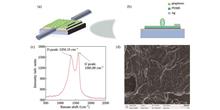
ObjectiveUltra-fast pulse fiber lasers are extensively employed in fields such as fiber optic communication, medicine, and precision material processing due to their compact structure and high beam quality. Lock mode technology is an effective method for achieving ultra-short pulses. Actively mode-locked lasers introduce active modulation devices into the laser cavity and adopt external modulation signals to change the optical signal characteristics, achieving a laser mode-locked pulse output. They feature flexibility, controllability, and stable output pulses. In recent years, graphene has been extensively studied due to its excellent electro-optical properties. Research has shown that an external electric field can alter the Fermi level of graphene to achieve light absorption modulation. Therefore, graphene-based electro-optic modulators have the potential to achieve actively mode-locked lasers. We present the construction of an efficient and high-speed graphene all-fiber mode-locked device, which achieves high-speed adjustment of graphene's optical performance with low modulation power consumption and high modulation efficiency.MethodsThe device is composed of graphene, single-mode optical fiber, polydimethylsiloxane (PDMS), and silver (Ag) film, forming a capacitive device (GCD) structure. By selecting glass as the substrate and leveraging magnetron sputtering technology to deposit 50 nm silver on the glass as the bottom electrode, silver has sound conductivity, which is beneficial for reducing the device resistance. The insulation layer is a spin-coated 200 nm PDMS layer, and the thinner insulation layer can effectively reduce the capacitance value of the device. Meanwhile, hydrofluoric acid (HF) with a concentration of 20% is utilized to corrode standard single-mode optical fibers to 15 µm with a corrosion length of 5 mm, and the corroded single-mode fiber is transferred to PDMS. The device is placed in a UV ozone cleaning machine (multi-frequency, CCI UV250-MC) for 10 minutes to improve the hydrophilicity of the insulation layer PDMS. There is graphene dispersion with a selected concentration of 0.1 mg/mL (Nanjing Xianfeng Nanomaterial Technology Co., Ltd., XFZ20 dispersion). Graphene solution is dropped onto the optical fiber, dried, and then inkjet printed with a silver electrode layer on the device using a microelectronic printer (Power Supply Technology Co., Ltd., MP1100). Finally, the prepared device is connected to the circuit board using silver wire. The GCD device is connected between the isolator and polarization controller by fusion, and a spectrum analyzer, digital oscilloscope, power meter, autocorrelator, and spectrum analyzer are adopted to record the locked pulse signal, including spectrum, pulse width, repetition rate, and output power.Results and DiscussionsThe GCD device is connected to the fiber laser system and a pump power of 80 mW is employed for actively mode-locked experiments. At a pump power of 80 mW, the AC signal amplitude increases from 0 V to 5 V, and the average output power decreases from 1.328 mW to 1.130 mW. After calculation, the insertion loss of the device increases from 1.54 dB to 2.46 dB (Fig. 4). Subsequently, a periodic AC signal (12.2 MHz) that is consistent with the resonant frequency of the laser cavity is applied to the graphene device. Under low voltage amplitude, the control of the graphene Fermi level is limited, resulting in a limited range of dynamic changes in the absorption of graphene devices. Therefore, unstable mode-locked pulse signals are observed. When the voltage amplitude increases to 5 V, the most stable mode-locked pulse signal is observed to achieve active mode locking of the laser. The narrowest pulse width of the mode locking signal is 298 ps (Fig. 5). Meanwhile, by increasing the modulation frequency to twice the resonant frequency of the laser cavity (24.4 MHz), the optical signal inside the cavity undergoes frequency doubling oscillation under the graphene device control, leading to harmonic mode-locked operation. The mode-locked pulse signal is slightly unstable, possibly due to the insufficient response speed of graphene to support the migration time of charge carriers at higher modulation rates, resulting in modulation depth changes in the device. This is also the reason for the wider pulse width of 315 ps, corresponding to a frequency of 24.4 MHz, which achieves active repetition frequency control in mode-locked lasers.ConclusionsWe introduce an actively mode-locked fiber laser based on a graphene all-fiber structure. It combines single-mode optical fibers that have undergone lateral corrosion treatment with graphene capacitor structures and utilize the evanescent wave coupling effect of optical fibers to interact with graphene, achieving efficient modulation. Meanwhile, by utilizing the inherent high carrier mobility of graphene, high-speed adjustment of optical performance can be achieved with lower modulation power consumption. The experimental results show that under a modulation signal of ±5 V, the fiber laser obtains controllable repetitive mode-locked pulses at a fixed pump power of 80 mW, with frequencies of 12.2 MHz and 24.4 MHz respectively. The corresponding mode-locked pulse widths are 298 ps and 315 ps respectively, and the laser center wavelength is 1558 nm. Meanwhile, by changing the amplitude of the AC signal (0-5 V), the average output power of the laser can be adjusted within the range of 1.328 mW to 1.130 mW. The research results provide references for achieving low-power and integrated actively mode-locked lasers, and have practical significance for developing efficient and integrated actively mode-locked laser systems. ObjectiveUltra-fast pulse fiber lasers are extensively employed in fields such as fiber optic communication, medicine, and precision material processing due to their compact structure and high beam quality. Lock mode technology is an effective method for achieving ultra-short pulses. Actively mode-locked lasers introduce active modulation devices into the laser cavity and adopt external modulation signals to change the optical signal characteristics, achieving a laser mode-locked pulse output. They feature flexibility, controllability, and stable output pulses. In recent years, graphene has been extensively studied due to its excellent electro-optical properties. Research has shown that an external electric field can alter the Fermi level of graphene to achieve light absorption modulation. Therefore, graphene-based electro-optic modulators have the potential to achieve actively mode-locked lasers. We present the construction of an efficient and high-speed graphene all-fiber mode-locked device, which achieves high-speed adjustment of graphene's optical performance with low modulation power consumption and high modulation efficiency.MethodsThe device is composed of graphene, single-mode optical fiber, polydimethylsiloxane (PDMS), and silver (Ag) film, forming a capacitive device (GCD) structure. By selecting glass as the substrate and leveraging magnetron sputtering technology to deposit 50 nm silver on the glass as the bottom electrode, silver has sound conductivity, which is beneficial for reducing the device resistance. The insulation layer is a spin-coated 200 nm PDMS layer, and the thinner insulation layer can effectively reduce the capacitance value of the device. Meanwhile, hydrofluoric acid (HF) with a concentration of 20% is utilized to corrode standard single-mode optical fibers to 15 µm with a corrosion length of 5 mm, and the corroded single-mode fiber is transferred to PDMS. The device is placed in a UV ozone cleaning machine (multi-frequency, CCI UV250-MC) for 10 minutes to improve the hydrophilicity of the insulation layer PDMS. There is graphene dispersion with a selected concentration of 0.1 mg/mL (Nanjing Xianfeng Nanomaterial Technology Co., Ltd., XFZ20 dispersion). Graphene solution is dropped onto the optical fiber, dried, and then inkjet printed with a silver electrode layer on the device using a microelectronic printer (Power Supply Technology Co., Ltd., MP1100). Finally, the prepared device is connected to the circuit board using silver wire. The GCD device is connected between the isolator and polarization controller by fusion, and a spectrum analyzer, digital oscilloscope, power meter, autocorrelator, and spectrum analyzer are adopted to record the locked pulse signal, including spectrum, pulse width, repetition rate, and output power.Results and DiscussionsThe GCD device is connected to the fiber laser system and a pump power of 80 mW is employed for actively mode-locked experiments. At a pump power of 80 mW, the AC signal amplitude increases from 0 V to 5 V, and the average output power decreases from 1.328 mW to 1.130 mW. After calculation, the insertion loss of the device increases from 1.54 dB to 2.46 dB (Fig. 4). Subsequently, a periodic AC signal (12.2 MHz) that is consistent with the resonant frequency of the laser cavity is applied to the graphene device. Under low voltage amplitude, the control of the graphene Fermi level is limited, resulting in a limited range of dynamic changes in the absorption of graphene devices. Therefore, unstable mode-locked pulse signals are observed. When the voltage amplitude increases to 5 V, the most stable mode-locked pulse signal is observed to achieve active mode locking of the laser. The narrowest pulse width of the mode locking signal is 298 ps (Fig. 5). Meanwhile, by increasing the modulation frequency to twice the resonant frequency of the laser cavity (24.4 MHz), the optical signal inside the cavity undergoes frequency doubling oscillation under the graphene device control, leading to harmonic mode-locked operation. The mode-locked pulse signal is slightly unstable, possibly due to the insufficient response speed of graphene to support the migration time of charge carriers at higher modulation rates, resulting in modulation depth changes in the device. This is also the reason for the wider pulse width of 315 ps, corresponding to a frequency of 24.4 MHz, which achieves active repetition frequency control in mode-locked lasers.ConclusionsWe introduce an actively mode-locked fiber laser based on a graphene all-fiber structure. It combines single-mode optical fibers that have undergone lateral corrosion treatment with graphene capacitor structures and utilize the evanescent wave coupling effect of optical fibers to interact with graphene, achieving efficient modulation. Meanwhile, by utilizing the inherent high carrier mobility of graphene, high-speed adjustment of optical performance can be achieved with lower modulation power consumption. The experimental results show that under a modulation signal of ±5 V, the fiber laser obtains controllable repetitive mode-locked pulses at a fixed pump power of 80 mW, with frequencies of 12.2 MHz and 24.4 MHz respectively. The corresponding mode-locked pulse widths are 298 ps and 315 ps respectively, and the laser center wavelength is 1558 nm. Meanwhile, by changing the amplitude of the AC signal (0-5 V), the average output power of the laser can be adjusted within the range of 1.328 mW to 1.130 mW. The research results provide references for achieving low-power and integrated actively mode-locked lasers, and have practical significance for developing efficient and integrated actively mode-locked laser systems.
Acta Optica Sinica
- Publication Date: Apr. 10, 2024
- Vol. 44, Issue 7, 0714001 (2024)
Performance of Short Micro-Cavity Structure for Underwater Fiber Nanosecond Laser Propulsion
Yang Ge, Hanyang Li, Hongtao Wang, Xianqi Tang, Gaoqian Zhou, and Xulong Yang
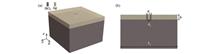
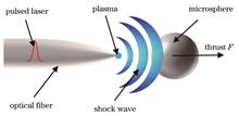
ObjectiveUnderwater laser plasma detonation wave propulsion technology has important application value in submarine stealth propulsion, detonation engine, supercavitation weapon systems, green ship manufacturing, and other fields. Different from the space focused laser induced propulsion method, the traditional laser propulsion system focuses on inherent defects such as insufficient energy gathering effect, difficult control of propulsion direction, and large laser loss. A new mode of underwater fiber laser induced plasma detonation wave propulsion is proposed, which achieves control of the laser focal point through the design of microcavity structure morphology coupled with fiber optics and research on the performance of fiber laser propulsion structure. Furthermore, the control of the movement direction of small particles entering and exiting can be achieved, which solves the problem of low energy coupling efficiency of laser plasma in underwater environments and difficulty in effectively applying propulsion force to the surface of the pushed object. By utilizing underwater plasma fiber laser induction to achieve directional propagation of detonation waves, we aim to improve the thrust and impulse coupling coefficient structural performance of laser propulsion. We focus on the morphology and energy conversion characteristics of fiber micro-cavity structures and the study provides theoretical support and guidance for future research on underwater laser induced plasma detonation wave dynamics while achieving particle targeting, fixed-point, and fixed-depth propulsion.MethodsWe utilize the theory and method of directional propagation of detonation waves through underwater fiber laser induced plasma, aiming to improve the thrust and impulse coupling coefficient structural performance of laser propulsion. Meanwhile, for the microcavity structural performance of underwater fiber laser propulsion, we combine the analysis of laser plasmon detonation theory to build a microstructure underwater laser plasma propulsion model and numerical simulation scheme. Simulation research is conducted by structural morphology and numerical characteristics. Firstly, to address the issues of low impulse coupling coefficient and divergent effects in underwater laser propulsion without microcavities, we numerically simulate the flow field when the microsphere is propagated by an underwater fiber laser under the same laser energy but different microsphere positions. This illustrates the necessity of adding structural constraints for underwater fiber laser propulsion and objecting the rust and pulse coupling coefficient without microcavities as a reference. Then, based on rectangular microcavities, we simulate the flow field of underwater fiber laser pulse for microcavities with different lengths and diameters while maintaining a constant distance between the microsphere and the laser focus. Finally, we conduct numerical simulations of the performance of open, U-shaped microcavities, double tube microcavities, and structures with blocking forces, aiming to establish a mapping relationship between the morphology of microcavities and the changes in the force and weight coupling coefficients of microspheres through comparative analysis of numerical results.Results and DiscussionsNumerical simulations yield the force curve and impulse coupling coefficient of the microsphere when the laser focus-to-microsphere distance changes without microcavities. The maximum impulse coupling coefficient is 0.117 dyne/W (Fig. 3), and the flow field situation of underwater fiber laser propulsion at 0.2 μs without micro cavities shows higher pressure in the symmetrical range of 30 to 90 degrees, indicating poor directional laser propulsion effects, which demonstrates the necessity of adding structural constraints (Fig. 4). By adding a rectangular microcavity, the impulse coupling coefficient can be improved to the order of 103 (Tables 1-2) compared to that without microcavities. However, as the microcavity length increases, the peak thrust decreases, reaching a maximum of about 140 dyne/W (Fig. 7). As the diameter increases, the impulse coupling coefficient increases, but the growth rate slows down (Fig. 9). The changes in force on the microsphere and the impulse coupling coefficient are obtained for U-shaped microcavities, double-tube microcavities, and microcavities with blocking structures. The U-shaped micro cavity increases the total applied force on the microsphere by approximately 0.002 N and improves the impulse coupling coefficient by 20 dyne/W (Fig. 12). When propelled by double-tube microcavities, the microsphere experiences a thrust of approximately 0.103 N and an impulse coupling coefficient of 340 dyne/W (Fig. 14). In the case of microcavities with blocking structures, the peak thrust is approximately 0.067 N, which represents a 44% increase (Fig. 17), while the impulse coupling coefficient is approximately 260 dyne/W, indicating an 86% increase (Table 3).ConclusionsWe propose several microcavity structures to solve the low impulse coupling coefficient and divergent effects of underwater fiber laser propulsion without microcavities. By conducting numerical simulations on the flow fields of different microcavity structures, we obtain the thrust curves and impulse coupling coefficients after adding the respective microcavities. The addition of rectangular microcavities can significantly improve the impulse coupling coefficient of underwater fiber laser propulsion to the order of 103 and concentrate the effects of laser propulsion. Meanwhile, when the distance between the laser focus and the microsphere remains constant, increasing the length of the microcavity decreases the peak thrust, while increasing the diameter increases the impulse coupling coefficient, albeit at a decreasing rate. Compared to rectangular microcavities, U-shaped microcavities, double-tube microcavities, and microcavities with blocking structures provide greater enhancements in force on the microsphere and impulse coupling coefficients. Among the four types of microcavities, double-tube microcavities show the greatest enhancement effect. The results demonstrate that the addition of microcavities can improve the efficiency of underwater fiber laser propulsion and provide corresponding enhancement effects for the four microcavity structures. ObjectiveUnderwater laser plasma detonation wave propulsion technology has important application value in submarine stealth propulsion, detonation engine, supercavitation weapon systems, green ship manufacturing, and other fields. Different from the space focused laser induced propulsion method, the traditional laser propulsion system focuses on inherent defects such as insufficient energy gathering effect, difficult control of propulsion direction, and large laser loss. A new mode of underwater fiber laser induced plasma detonation wave propulsion is proposed, which achieves control of the laser focal point through the design of microcavity structure morphology coupled with fiber optics and research on the performance of fiber laser propulsion structure. Furthermore, the control of the movement direction of small particles entering and exiting can be achieved, which solves the problem of low energy coupling efficiency of laser plasma in underwater environments and difficulty in effectively applying propulsion force to the surface of the pushed object. By utilizing underwater plasma fiber laser induction to achieve directional propagation of detonation waves, we aim to improve the thrust and impulse coupling coefficient structural performance of laser propulsion. We focus on the morphology and energy conversion characteristics of fiber micro-cavity structures and the study provides theoretical support and guidance for future research on underwater laser induced plasma detonation wave dynamics while achieving particle targeting, fixed-point, and fixed-depth propulsion.MethodsWe utilize the theory and method of directional propagation of detonation waves through underwater fiber laser induced plasma, aiming to improve the thrust and impulse coupling coefficient structural performance of laser propulsion. Meanwhile, for the microcavity structural performance of underwater fiber laser propulsion, we combine the analysis of laser plasmon detonation theory to build a microstructure underwater laser plasma propulsion model and numerical simulation scheme. Simulation research is conducted by structural morphology and numerical characteristics. Firstly, to address the issues of low impulse coupling coefficient and divergent effects in underwater laser propulsion without microcavities, we numerically simulate the flow field when the microsphere is propagated by an underwater fiber laser under the same laser energy but different microsphere positions. This illustrates the necessity of adding structural constraints for underwater fiber laser propulsion and objecting the rust and pulse coupling coefficient without microcavities as a reference. Then, based on rectangular microcavities, we simulate the flow field of underwater fiber laser pulse for microcavities with different lengths and diameters while maintaining a constant distance between the microsphere and the laser focus. Finally, we conduct numerical simulations of the performance of open, U-shaped microcavities, double tube microcavities, and structures with blocking forces, aiming to establish a mapping relationship between the morphology of microcavities and the changes in the force and weight coupling coefficients of microspheres through comparative analysis of numerical results.Results and DiscussionsNumerical simulations yield the force curve and impulse coupling coefficient of the microsphere when the laser focus-to-microsphere distance changes without microcavities. The maximum impulse coupling coefficient is 0.117 dyne/W (Fig. 3), and the flow field situation of underwater fiber laser propulsion at 0.2 μs without micro cavities shows higher pressure in the symmetrical range of 30 to 90 degrees, indicating poor directional laser propulsion effects, which demonstrates the necessity of adding structural constraints (Fig. 4). By adding a rectangular microcavity, the impulse coupling coefficient can be improved to the order of 103 (Tables 1-2) compared to that without microcavities. However, as the microcavity length increases, the peak thrust decreases, reaching a maximum of about 140 dyne/W (Fig. 7). As the diameter increases, the impulse coupling coefficient increases, but the growth rate slows down (Fig. 9). The changes in force on the microsphere and the impulse coupling coefficient are obtained for U-shaped microcavities, double-tube microcavities, and microcavities with blocking structures. The U-shaped micro cavity increases the total applied force on the microsphere by approximately 0.002 N and improves the impulse coupling coefficient by 20 dyne/W (Fig. 12). When propelled by double-tube microcavities, the microsphere experiences a thrust of approximately 0.103 N and an impulse coupling coefficient of 340 dyne/W (Fig. 14). In the case of microcavities with blocking structures, the peak thrust is approximately 0.067 N, which represents a 44% increase (Fig. 17), while the impulse coupling coefficient is approximately 260 dyne/W, indicating an 86% increase (Table 3).ConclusionsWe propose several microcavity structures to solve the low impulse coupling coefficient and divergent effects of underwater fiber laser propulsion without microcavities. By conducting numerical simulations on the flow fields of different microcavity structures, we obtain the thrust curves and impulse coupling coefficients after adding the respective microcavities. The addition of rectangular microcavities can significantly improve the impulse coupling coefficient of underwater fiber laser propulsion to the order of 103 and concentrate the effects of laser propulsion. Meanwhile, when the distance between the laser focus and the microsphere remains constant, increasing the length of the microcavity decreases the peak thrust, while increasing the diameter increases the impulse coupling coefficient, albeit at a decreasing rate. Compared to rectangular microcavities, U-shaped microcavities, double-tube microcavities, and microcavities with blocking structures provide greater enhancements in force on the microsphere and impulse coupling coefficients. Among the four types of microcavities, double-tube microcavities show the greatest enhancement effect. The results demonstrate that the addition of microcavities can improve the efficiency of underwater fiber laser propulsion and provide corresponding enhancement effects for the four microcavity structures.
Acta Optica Sinica
- Publication Date: Mar. 25, 2024
- Vol. 44, Issue 6, 0614001 (2024)

High-Speed Center Wavelength Tuning of Narrow-Spectrum Passively Mode-Locked Fiber Laser and Its Pulse Reconstruction Process
Zhe Zhu, Luyi Wang, Xuewen Chen, Wei Lin, Yang Yang, Jing Zhang, Tao Liu, Xiaoming Wei, and Zhongmin Yang
ObjectiveAfter decades of development, mode-locked fiber lasers can provide laser pulses with high coherence, high pulse energy, and controllable pulse width and repetition rate. Mode-locked pulsed lasers can play a key role in some specific research areas. For instance, in biomedicine, lasers are used as light sources to perform coherent tomography imaging and the information of the samples under test can be collected and recorded at the same time. However, in the process, the signals of some substances with similar excitation wavelengths can interfere with each other, thus affecting the measurement results. Therefore, the development of wavelength tunable mode-locked lasers to improve spectral resolution is of great significance to the research in this field. We study the rapid tuning of the center wavelength of a narrow-spectrum passive mode-locked ytterbium fiber laser based on fast acousto-optic filtering technology. Combining fast acousto-optic filtering technology, we obtain a stable mode-locked pulse with a center wavelength tuning function. To investigate the reconstruction process of laser pulses during intracavity filtering and confirm the reliability of this technology, we record the real-time reconstruction process of laser pulses during the tuning of the center wavelength. We hope that our research can provide a reliable solution for applications requiring high spectral resolution.MethodsThe laser consists of a laser cavity and a two-stage amplifier. The fiber cavity consists of a semiconductor saturable absorption mirror (SESAM), a wavelength division multiplexer (WDM), a 40 cm long ytterbium-doped fiber (CorActive Yb406, YDF), a 90∶10 fiber coupler (90∶10 OC), a collimator, and a λ/2 waveplate (HWP). It is composed of acousto-optic tunable filter, reflect mirror, and piezoelectric ceramic transducer (PZT). The piezoelectric ceramic is combined with a mirror to lock and stabilize the output laser repetition rate by adjusting the length of the phase-locked loop feedback. The phase-locked loop is composed of a photodetector (PD), an RF amplifier, a bandpass filter, a mixer, a signal source, a low pass filter, and a proportional integral derivative (PID). The voltage intensity of the externally modulated signal can alter the intracavity pumping energy. The rising edge of the modulated signal can be recognized by the acousto-optic tunable filter driver and used to switch the filter wavelength. The arbitrary waveform generator drives the acousto-optic tunable filter and laser semiconductor with the edited modulation signal, such that the center wavelength of the laser can be tuned at high speed while maintaining the mode-locked state. To explore the pulse conversion process in the cavity during wavelength switching, a part of the laser after the first stage amplification is fed into the dispersion compensation fiber, and the stretched optical signal is converted into an electrical signal through a photodetector and transmitted to a high-speed oscilloscope. The real-time observation of the laser pulse reconstruction process can be realized by generating signals through the external arbitrary signal generator, and simultaneously modulating the pump working current of the cavity and the wavelength switching of the acousto-optic tunable filter.Results and DiscussionsThe parameters of the laser are tested (Figs. 2 and 3), and the wavelength tuning ability and frequency stability of the laser are verified (Fig. 4). The phase noise and time jitter of the locked pulse are significantly improved. The time jitter of the locked laser is 9.58 ps, and the phase noise at 10 Hz is -72 dBc/Hz. The information on the pulse reconstruction process of the laser in the state of high pump power and the operation of the single pulse after adjusting the external modulation signal is recorded (Figs. 5 and 6). The information shows the pulse reconstruction time and spectrum of the wavelength tuning process. The spectral stability and the highest wavelength tuning speed can be defined. Also, the result of the dispersive Fourier transform test proves that by editing the external modulation signal to change the internal pump energy of the laser cavity and the filtering band of the acousto-optic tunable filter, a reliable mode-locked fiber laser with high-speed tuning of the center wavelength can be obtained.ConclusionsWe study the rapid tuning of the center wavelength of a narrow-spectrum passive mode-locked ytterbium fiber laser based on fast acousto-optic filtering technology. The narrow-spectrum mode-locked fiber laser system has an output power of 200 mW, a pulse width of 5.87 ps, a repetition rate of 40.874 MHz, and a spectral bandwidth of 0.15 nm. By programming the RF signal to drive the acousto-optic tunable filter, a stable mode-locked pulse with a center wavelength tunable in the range of 1016-1042 nm can be obtained. To investigate the reconstruction process of laser pulses during intracavity filtering, we employ the dispersive Fourier transform technology to visualize the real-time reconstruction process of laser pulses during the tuning of the center wavelength, and the results confirm that the highest central wavelength tuning frequency of the laser is about 5 kHz. ObjectiveAfter decades of development, mode-locked fiber lasers can provide laser pulses with high coherence, high pulse energy, and controllable pulse width and repetition rate. Mode-locked pulsed lasers can play a key role in some specific research areas. For instance, in biomedicine, lasers are used as light sources to perform coherent tomography imaging and the information of the samples under test can be collected and recorded at the same time. However, in the process, the signals of some substances with similar excitation wavelengths can interfere with each other, thus affecting the measurement results. Therefore, the development of wavelength tunable mode-locked lasers to improve spectral resolution is of great significance to the research in this field. We study the rapid tuning of the center wavelength of a narrow-spectrum passive mode-locked ytterbium fiber laser based on fast acousto-optic filtering technology. Combining fast acousto-optic filtering technology, we obtain a stable mode-locked pulse with a center wavelength tuning function. To investigate the reconstruction process of laser pulses during intracavity filtering and confirm the reliability of this technology, we record the real-time reconstruction process of laser pulses during the tuning of the center wavelength. We hope that our research can provide a reliable solution for applications requiring high spectral resolution.MethodsThe laser consists of a laser cavity and a two-stage amplifier. The fiber cavity consists of a semiconductor saturable absorption mirror (SESAM), a wavelength division multiplexer (WDM), a 40 cm long ytterbium-doped fiber (CorActive Yb406, YDF), a 90∶10 fiber coupler (90∶10 OC), a collimator, and a λ/2 waveplate (HWP). It is composed of acousto-optic tunable filter, reflect mirror, and piezoelectric ceramic transducer (PZT). The piezoelectric ceramic is combined with a mirror to lock and stabilize the output laser repetition rate by adjusting the length of the phase-locked loop feedback. The phase-locked loop is composed of a photodetector (PD), an RF amplifier, a bandpass filter, a mixer, a signal source, a low pass filter, and a proportional integral derivative (PID). The voltage intensity of the externally modulated signal can alter the intracavity pumping energy. The rising edge of the modulated signal can be recognized by the acousto-optic tunable filter driver and used to switch the filter wavelength. The arbitrary waveform generator drives the acousto-optic tunable filter and laser semiconductor with the edited modulation signal, such that the center wavelength of the laser can be tuned at high speed while maintaining the mode-locked state. To explore the pulse conversion process in the cavity during wavelength switching, a part of the laser after the first stage amplification is fed into the dispersion compensation fiber, and the stretched optical signal is converted into an electrical signal through a photodetector and transmitted to a high-speed oscilloscope. The real-time observation of the laser pulse reconstruction process can be realized by generating signals through the external arbitrary signal generator, and simultaneously modulating the pump working current of the cavity and the wavelength switching of the acousto-optic tunable filter.Results and DiscussionsThe parameters of the laser are tested (Figs. 2 and 3), and the wavelength tuning ability and frequency stability of the laser are verified (Fig. 4). The phase noise and time jitter of the locked pulse are significantly improved. The time jitter of the locked laser is 9.58 ps, and the phase noise at 10 Hz is -72 dBc/Hz. The information on the pulse reconstruction process of the laser in the state of high pump power and the operation of the single pulse after adjusting the external modulation signal is recorded (Figs. 5 and 6). The information shows the pulse reconstruction time and spectrum of the wavelength tuning process. The spectral stability and the highest wavelength tuning speed can be defined. Also, the result of the dispersive Fourier transform test proves that by editing the external modulation signal to change the internal pump energy of the laser cavity and the filtering band of the acousto-optic tunable filter, a reliable mode-locked fiber laser with high-speed tuning of the center wavelength can be obtained.ConclusionsWe study the rapid tuning of the center wavelength of a narrow-spectrum passive mode-locked ytterbium fiber laser based on fast acousto-optic filtering technology. The narrow-spectrum mode-locked fiber laser system has an output power of 200 mW, a pulse width of 5.87 ps, a repetition rate of 40.874 MHz, and a spectral bandwidth of 0.15 nm. By programming the RF signal to drive the acousto-optic tunable filter, a stable mode-locked pulse with a center wavelength tunable in the range of 1016-1042 nm can be obtained. To investigate the reconstruction process of laser pulses during intracavity filtering, we employ the dispersive Fourier transform technology to visualize the real-time reconstruction process of laser pulses during the tuning of the center wavelength, and the results confirm that the highest central wavelength tuning frequency of the laser is about 5 kHz.
Acta Optica Sinica
- Publication Date: Mar. 10, 2024
- Vol. 44, Issue 5, 0514001 (2024)
Numerical Simulation and Experimental Optimization of Pulse Laser Processing Carbon Fiber Reinforced Polymer Plate
Song Cai, Jinchao Song, Da Chen, Yuebing Wen, Zhijian He, Nengru Tao, and Guoqi He
ObjectiveThe thermal properties during pulse laser processing of carbon fiber reinforced polymer (CFRP) are significant for optimizing process parameters and strategies. An important factor in laser ablation of CFRP materials is the temperature rise caused by carbon fiber absorption of light. However, most of them employ computer-aided design software to simulate the internal temperature field of materials presently, with few underlying algorithms for heat transfer simulation. We study the ablation of the CFRP plate by optical fiber pulse infrared laser, build a new heat transfer model, and carry out the numerical analysis and the laser ablation experiment of the CFRP plate. The experimental results show that the theoretical model is correct and feasible, thus providing references for laser processing research of CFRP materials.MethodsDuring laser CFRP plate processing, the laser beams have a certain moving speed. According to this characteristic, a linear Gauss heat source is proposed to simulate the moving temperature field of laser ablation. Based on the Fourier heat transfer model, the heat transfer physical model of the nanosecond pulse laser processing CFRP plate is built, and the finite difference time domain method is adopted to analyze the model. The laser ablation of the isosceles triangle pattern in a 0.5 mm thick CFRP plate is conducted by nanosecond pulse lasers. Then, the surface roughness data after ablation is obtained by a surface roughness tester. According to the above experimental results, we verify the correctness and feasibility of the model and obtain sound process parameters of laser processing CFRP.Results and DiscussionsThe MATLAB numerical analysis temperature simulation results and comparative analysis on corresponding parameters of the ultra-depth-of-field photos are presented. Fig. 10(a) shows the surface morphology of the CFRP plate when the laser power is 1 W. At this time, the maximum temperature of the material surface [470 K, Fig. 1(a)] is close to the resin decomposition temperature. The resin presents a molten state on the tow area of parallel arranged carbon fiber and then solidifies along the carbon fiber arrangement structure. Part of the molten resin penetrates the gap of the carbon fiber, while the carbon fiber has little change. Fig. 10(b) shows the surface morphology of the CFRP plate under the laser power of 5 W. At this time, the maximum temperature of the CFRP plate surface is 1158 K [Fig. 1(b)], which surpasses the decomposition temperature and gasification temperature of the resin material. The thicker part of the resin surface layer does not evaporate and is also affected by the thermal expansion pressure to form curved resin layer fragments, which is inserted into the air. When the laser power increases to 9 W, as shown in Fig. 10(c), the highest surface temperature of the CFRP plate is as high as 1500 K [Fig. 1(c)], which greatly surpasses the resin gasification temperature and exceeds the carbon fiber decomposition temperature (1153 K). The thicker resin layer is largely evaporated, but there is still a small amount of residue. Meanwhile, we decompose a small amount of carbon fibers, break the carbon filament, and expose it to the air. The evolution rule of surface roughness and the sample variance of performance data stability with laser power and laser scanning speed are shown in Fig. 14. Under the scanning speed of 200 mm/s, the performance data stability is sound and the sample variance is 1.889. At the scanning speed of 200 mm/s and laser power P=9 W, the CFRP surface temperature increases, and the epoxy resin is evaporated, with the surface roughness decreasing to 7.20 μm. According to the evolution law of CFRP material ablation quality, when the laser power and laser scanning speed are 9 W and 200 mm/s respectively, the ablation quality of CFRP materials processed by nanosecond pulse lasers is ideal.ConclusionsBased on the linear velocity of laser beams, we build a heat transfer model of filament Gauss heat source for nanosecond pulse laser ablation of CFRP materials. The model only requires parameters such as laser and material properties, and its numerical simulation results are compared with the surface topography photos obtained by the super depth of field three-dimensional microscope. The experimental results are consistent with the numerical analysis results, which verifies the correctness and feasibility of the numerical simulation. This model is universal and widely applicable to provide theoretical guidance for heat transfer research on the surface of laser ablated materials. The combination experiment of laser ablation parameters for CFRP plates is carried out. The surface roughness of the ablated plate is measured with a roughness detector. The results show that good processing performance can be obtained under the laser power of 9 W and laser scanning speed of 200 mm/s. At this time, the surface roughness and sample variance are 7.20 μm and 1.889 respectively. ObjectiveThe thermal properties during pulse laser processing of carbon fiber reinforced polymer (CFRP) are significant for optimizing process parameters and strategies. An important factor in laser ablation of CFRP materials is the temperature rise caused by carbon fiber absorption of light. However, most of them employ computer-aided design software to simulate the internal temperature field of materials presently, with few underlying algorithms for heat transfer simulation. We study the ablation of the CFRP plate by optical fiber pulse infrared laser, build a new heat transfer model, and carry out the numerical analysis and the laser ablation experiment of the CFRP plate. The experimental results show that the theoretical model is correct and feasible, thus providing references for laser processing research of CFRP materials.MethodsDuring laser CFRP plate processing, the laser beams have a certain moving speed. According to this characteristic, a linear Gauss heat source is proposed to simulate the moving temperature field of laser ablation. Based on the Fourier heat transfer model, the heat transfer physical model of the nanosecond pulse laser processing CFRP plate is built, and the finite difference time domain method is adopted to analyze the model. The laser ablation of the isosceles triangle pattern in a 0.5 mm thick CFRP plate is conducted by nanosecond pulse lasers. Then, the surface roughness data after ablation is obtained by a surface roughness tester. According to the above experimental results, we verify the correctness and feasibility of the model and obtain sound process parameters of laser processing CFRP.Results and DiscussionsThe MATLAB numerical analysis temperature simulation results and comparative analysis on corresponding parameters of the ultra-depth-of-field photos are presented. Fig. 10(a) shows the surface morphology of the CFRP plate when the laser power is 1 W. At this time, the maximum temperature of the material surface [470 K, Fig. 1(a)] is close to the resin decomposition temperature. The resin presents a molten state on the tow area of parallel arranged carbon fiber and then solidifies along the carbon fiber arrangement structure. Part of the molten resin penetrates the gap of the carbon fiber, while the carbon fiber has little change. Fig. 10(b) shows the surface morphology of the CFRP plate under the laser power of 5 W. At this time, the maximum temperature of the CFRP plate surface is 1158 K [Fig. 1(b)], which surpasses the decomposition temperature and gasification temperature of the resin material. The thicker part of the resin surface layer does not evaporate and is also affected by the thermal expansion pressure to form curved resin layer fragments, which is inserted into the air. When the laser power increases to 9 W, as shown in Fig. 10(c), the highest surface temperature of the CFRP plate is as high as 1500 K [Fig. 1(c)], which greatly surpasses the resin gasification temperature and exceeds the carbon fiber decomposition temperature (1153 K). The thicker resin layer is largely evaporated, but there is still a small amount of residue. Meanwhile, we decompose a small amount of carbon fibers, break the carbon filament, and expose it to the air. The evolution rule of surface roughness and the sample variance of performance data stability with laser power and laser scanning speed are shown in Fig. 14. Under the scanning speed of 200 mm/s, the performance data stability is sound and the sample variance is 1.889. At the scanning speed of 200 mm/s and laser power P=9 W, the CFRP surface temperature increases, and the epoxy resin is evaporated, with the surface roughness decreasing to 7.20 μm. According to the evolution law of CFRP material ablation quality, when the laser power and laser scanning speed are 9 W and 200 mm/s respectively, the ablation quality of CFRP materials processed by nanosecond pulse lasers is ideal.ConclusionsBased on the linear velocity of laser beams, we build a heat transfer model of filament Gauss heat source for nanosecond pulse laser ablation of CFRP materials. The model only requires parameters such as laser and material properties, and its numerical simulation results are compared with the surface topography photos obtained by the super depth of field three-dimensional microscope. The experimental results are consistent with the numerical analysis results, which verifies the correctness and feasibility of the numerical simulation. This model is universal and widely applicable to provide theoretical guidance for heat transfer research on the surface of laser ablated materials. The combination experiment of laser ablation parameters for CFRP plates is carried out. The surface roughness of the ablated plate is measured with a roughness detector. The results show that good processing performance can be obtained under the laser power of 9 W and laser scanning speed of 200 mm/s. At this time, the surface roughness and sample variance are 7.20 μm and 1.889 respectively.
Acta Optica Sinica
- Publication Date: Feb. 10, 2024
- Vol. 44, Issue 3, 0314002 (2024)
Design and Simulation of Optical Field in Quasi-Two-Dimensional Isotropic Laser Cooling
Xiao Zhang, Xin Wang, Wenli Wang, Yuan Sun, and Liang Liu
ObjectiveIsotropic laser cooling is regarded as one of the crucial laser cooling techniques because of its distinctive benefits including simplicity, compactness, and robustness. It has been extensively applied in areas including atomic microwave clocks, quantum simulation, and quantum sensing. As a distinct distribution type of cold atoms in isotropic laser cooling, cold atoms with quasi-two-dimensional distributions have significant applications and usefulness in fields of study, including atomic cooling and quantum precision measurement. Isotropic laser cooling does not restrict atoms, different from techniques like magneto-optical traps. The distributions of the optical field and the cold atoms inside the cavity are significantly influenced by the laser injection methodology and cavity design. To obtain cold atoms with a quasi-two-dimensional distribution, one must effectively establish a uniformly distributed quasi-two-dimensional optical field in a flat cavity. In order to get a uniform optical field, we explore the impact of various incident optical field parameters on the optical field distribution using optical simulations to study how to produce a quasi-two-dimensional optical field distribution.MethodsThe main method for creating a nearly two-dimensional optical field in a flat cavity is the subject of this study. We propose a flat diffusion cavity-based cavity structure for the first time. It models the effects of two alternative injection techniques, namely free-space injection and optical fiber injection, on the optical field distribution using optical simulation software. Using the optical fiber injection technique as a foundation, we explore how changing the angle of injection affects the way the light field is distributed inside the cavity. We also investigate the distribution of the optical field inside the cavity as a function of important optical fiber characteristics, particularly the numerical aperture and core diameter. Finally, we investigate the relationship between differences in the optical field distribution inside the cavity and variations in cavity diameters, and this demonstrates that by adjusting these factors, we may significantly improve the optical field's homogeneity.Results and DiscussionsThe simulation results show that the optical fiber injection method is superior to the free-space optical injection strategy in producing a homogeneous optical field within the flat diffuse-reflectance cavity (Fig. 4). Furthermore, by modifying particular parameters, the optical field may be optimized. The homogeneity of the optical field is improved to some extent when the angle of incidence of the optical fiber rotates within reasonable bounds. To keep a uniform optical field distribution, it is crucial to prevent large angle variations (Fig. 5). While changes in core diameter have relatively little influence on the optical field distribution, variations in numerical aperture have a large impact on the uniformity of the optical field (Fig. 6). As a result, choosing an optical fiber with the right specifications is essential for improving the homogeneity of the optical field. Due to structural modifications, increasing the cavity height while keeping the proper height enhances the optical field dispersion. Sometimes, it even improves the optical power density at particular locations. The optical power density distribution within the cavity, however, shows a declining tendency with an overall rise in height (Fig. 7). With a rising side length scaling factor, the optical power density inside the cavity displays a negative power-law relationship decrease pattern. The power consumption for the incident cooling light therefore grows dramatically as the cavity volume expands, even with the same optical power density requirements (Fig. 8).ConclusionsEstablishing a uniform optical power density distribution is a difficult point in studies designed to achieve a quasi-two-dimensional distribution of cold atoms within a flat diffuse-reflectance cavity. We simulate several cooling light injection strategies. When optical fiber injection is utilized instead of free-space optical injection, the optical field distribution is more uniform. The flatness of the optical field can be optimized within particular locations by adjusting the angle of incidence of the optical cable. The optical field's homogeneity is also strongly impacted by the optical fiber's numerical aperture. The initial beam diameter and divergence angle of the incident light are both determined by the numerical aperture and core diameter of the optical fiber. The flatness of the optical field can be improved within certain geographic areas by using optical fibers with the right characteristics. The optical power density inside the cavity shows a negative exponential drop trend as the cavity volume grows. These simulation findings offer helpful pointers for attaining a very homogeneous and quasi-two-dimensional optical field distribution. They also clarify the connection between variations in cavity size and the optical field distribution in the context of isotropic laser cooling. ObjectiveIsotropic laser cooling is regarded as one of the crucial laser cooling techniques because of its distinctive benefits including simplicity, compactness, and robustness. It has been extensively applied in areas including atomic microwave clocks, quantum simulation, and quantum sensing. As a distinct distribution type of cold atoms in isotropic laser cooling, cold atoms with quasi-two-dimensional distributions have significant applications and usefulness in fields of study, including atomic cooling and quantum precision measurement. Isotropic laser cooling does not restrict atoms, different from techniques like magneto-optical traps. The distributions of the optical field and the cold atoms inside the cavity are significantly influenced by the laser injection methodology and cavity design. To obtain cold atoms with a quasi-two-dimensional distribution, one must effectively establish a uniformly distributed quasi-two-dimensional optical field in a flat cavity. In order to get a uniform optical field, we explore the impact of various incident optical field parameters on the optical field distribution using optical simulations to study how to produce a quasi-two-dimensional optical field distribution.MethodsThe main method for creating a nearly two-dimensional optical field in a flat cavity is the subject of this study. We propose a flat diffusion cavity-based cavity structure for the first time. It models the effects of two alternative injection techniques, namely free-space injection and optical fiber injection, on the optical field distribution using optical simulation software. Using the optical fiber injection technique as a foundation, we explore how changing the angle of injection affects the way the light field is distributed inside the cavity. We also investigate the distribution of the optical field inside the cavity as a function of important optical fiber characteristics, particularly the numerical aperture and core diameter. Finally, we investigate the relationship between differences in the optical field distribution inside the cavity and variations in cavity diameters, and this demonstrates that by adjusting these factors, we may significantly improve the optical field's homogeneity.Results and DiscussionsThe simulation results show that the optical fiber injection method is superior to the free-space optical injection strategy in producing a homogeneous optical field within the flat diffuse-reflectance cavity (Fig. 4). Furthermore, by modifying particular parameters, the optical field may be optimized. The homogeneity of the optical field is improved to some extent when the angle of incidence of the optical fiber rotates within reasonable bounds. To keep a uniform optical field distribution, it is crucial to prevent large angle variations (Fig. 5). While changes in core diameter have relatively little influence on the optical field distribution, variations in numerical aperture have a large impact on the uniformity of the optical field (Fig. 6). As a result, choosing an optical fiber with the right specifications is essential for improving the homogeneity of the optical field. Due to structural modifications, increasing the cavity height while keeping the proper height enhances the optical field dispersion. Sometimes, it even improves the optical power density at particular locations. The optical power density distribution within the cavity, however, shows a declining tendency with an overall rise in height (Fig. 7). With a rising side length scaling factor, the optical power density inside the cavity displays a negative power-law relationship decrease pattern. The power consumption for the incident cooling light therefore grows dramatically as the cavity volume expands, even with the same optical power density requirements (Fig. 8).ConclusionsEstablishing a uniform optical power density distribution is a difficult point in studies designed to achieve a quasi-two-dimensional distribution of cold atoms within a flat diffuse-reflectance cavity. We simulate several cooling light injection strategies. When optical fiber injection is utilized instead of free-space optical injection, the optical field distribution is more uniform. The flatness of the optical field can be optimized within particular locations by adjusting the angle of incidence of the optical cable. The optical field's homogeneity is also strongly impacted by the optical fiber's numerical aperture. The initial beam diameter and divergence angle of the incident light are both determined by the numerical aperture and core diameter of the optical fiber. The flatness of the optical field can be improved within certain geographic areas by using optical fibers with the right characteristics. The optical power density inside the cavity shows a negative exponential drop trend as the cavity volume grows. These simulation findings offer helpful pointers for attaining a very homogeneous and quasi-two-dimensional optical field distribution. They also clarify the connection between variations in cavity size and the optical field distribution in the context of isotropic laser cooling.
Acta Optica Sinica
- Publication Date: Feb. 10, 2024
- Vol. 44, Issue 3, 0314001 (2024)
High-Power 1060 nm Vertical Cavity Surface Emitting Laser
Meiyin Zheng, Hongwei Qu, Xuyan Zhou, Fengxin Dong, Jianxin Zhang, Jiatong Sui, Fansheng Meng, Zhonghua Xie, Hailing Wang, Yufei Wang, and Aiyi Qi
ObjectiveVertical cavity surface emitting laser (VCSEL) has advantages such as low threshold, single longitudinal mode, circular symmetric spot, high efficiency, high modulation rate, small size, easy two-dimensional integration, and low cost. Therefore, it is widely used in optical communication, infrared lighting, and medical fields. The research on 1060 nm VCSEL in China and abroad mainly focuses on the field of low-power and low-loss optical communication, while there are few reports on high-power 1060 nm VCSEL. The 1060 nm VCSEL is mainly composed of the active region and top and down distributed Bragg reflectors (DBRs). Due to the high composition of InGaAs quantum wells, excessive strain can easily lead to poor material growth quality in the active region. Thus, strain-compensated quantum well active region and the DBR structural parameters will affect the output power and efficiency of the VCSEL. It is necessary to optimize the design of the strain-compensated quantum well active region and DBR structure to improve the performance of the 1060 nm VCSEL. We optimize the overall structure of the 1060 nm VCSEL epitaxial structure. In addition, we compare quantum wells of six different InGaAs components and thicknesses and analyze the gain and output characteristics of three barrier materials in the quantum well active region. We optimize the DBR for different gradient layer thicknesses and pairs. VCSEL single and array characteristics are fabricated and tested experimentally.MethodsThe red-shift velocity of the 1060 nm VCSEL is calculated to be 0.40 nm/K by PICS3D simulation software to determine the appropriate gain and cavity mode mismatch of -20 nm. By comparing and analyzing the gain spectra and peak gain of six different InGaAs components and thicknesses with temperature changes, as well as the output power, it is simulated that the In0.28Ga0.72As quantum well with a thickness of 8 nm has better gain and output characteristics at high temperatures. Serious carrier leakage from too-thin quantum wells and low peak gain for too-thick ones are unfavorable for improving output characteristics. The peak gain of GaAs0.8P0.2, Al0.1Ga0.9As, and GaAs barrier layers is compared with temperature changes, transparent carrier concentration, and output power. It is shown that the 10 nm GaAs0.8P0.2 barrier material has a lower threshold, higher output power, and high-temperature characteristics. Under 30 mA injection current, the output power of a 15 μm oxide aperture VCSEL device with GaAs0.8P0.2 barrier layer is 21.95 mW. We simulate and calculate the DBR reflection spectrum bandwidth, reflection spectrum, and reflectivity of different DBR pairs for different gradient layer thicknesses, providing theoretical guidance for optimal design. The simulation results show that the P-DBR gradient layer thickness of 20 nm and the DBR pairs of 18 pairs are beneficial for reducing series resistance and improving output power. VCSEL epitaxial structures in the active region of In0.28Ga0.72As/GaAs0.8P0.2 quantum wells are grown using metal organic chemical vapor deposition (MOCVD), and corresponding VCSEL single and arrays are experimentally fabricated.Results and DiscussionsFabrication and packaging testing of 1060 nm VCSEL single are conducted. The experimental measurement shows that the 1060 nm VCSEL single element of 15μm has a continuous output power of 20 mW at 30 mA and a threshold current of 1.6 mA [Fig. 7(a)]. The experimental and theoretical results are consistent, that is, the 8 nm thick In0.28Ga0.72As well layer and the 10 nm thick GaAs0.8P0.2 barrier layer have better temperature and output characteristics. For the 288-element 1060 nm VCSEL array, the continuous output power is 2.62 W at 4.5 A, and the maximum electro-optical conversion efficiency is 36.8% [Fig. 7(b)]. Under quasi-continuous conditions (pulse width is 100 μs and duty cycle is 1%), the 5 mm×5 mm 1060 nm VCSEL array has a peak power of 53.4 W at 100 A [Fig. 7(c)]. The spectra of 288-element arrays are tested at different currents. Under continuous operating conditions at room temperature, the peak wavelengths of the VCSEL array are 1063.2, 1063.7, 1064.3, 1065.7, and 1067.2 nm, respectively, at currents of 0.5, 1.5, 2.5, 3.5, and 4.5 A (Fig. 8). Based on the temperature drift coefficient of the VCSEL wavelength, which is about 0.065 nm/K, the temperature rise of the VCSEL array is calculated to be 61.54 °C when the current increases from 0.5 to 4.5 A.ConclusionsIn this paper, theoretical simulation and experimental research are implemented on the high-power and high-efficiency 1060 nm VCSEL. Epitaxial structure parameters such as In0.28Ga0.72As/GaAs0.8P0.2 quantum well active region parameters and DBR parameters with better output characteristics are obtained by considering the gain characteristics, transparent carrier concentration, and series resistance. VCSELs with InGaAs/GaAsP strain compensated quantum well structures are grown by metal organic chemical vapor deposition technology, and single and array VCSELs are fabricated. The experimental data and theoretical analysis are consistent. Experimental measurement shows that the 1060 nm VCSEL single element of 15 μm oxidation aperture continuous output power is 20 mW at 30 mA. For the 288-element 1060 nm VCSEL array, the continuous output power is 2.62 W at 4.5 A, and the maximum electro-optical conversion efficiency is 36.8%. Under quasi-continuous conditions (pulse width is 100 μs and duty cycle is 1%), the 5 mm×5 mm 1060 nm VCSEL array has a peak power of 53.4 W at 100 A. The related theoretical simulation work is a good theoretical guide for achieving high-power, high-efficiency, and low-threshold 1060 nm VCSELs. ObjectiveVertical cavity surface emitting laser (VCSEL) has advantages such as low threshold, single longitudinal mode, circular symmetric spot, high efficiency, high modulation rate, small size, easy two-dimensional integration, and low cost. Therefore, it is widely used in optical communication, infrared lighting, and medical fields. The research on 1060 nm VCSEL in China and abroad mainly focuses on the field of low-power and low-loss optical communication, while there are few reports on high-power 1060 nm VCSEL. The 1060 nm VCSEL is mainly composed of the active region and top and down distributed Bragg reflectors (DBRs). Due to the high composition of InGaAs quantum wells, excessive strain can easily lead to poor material growth quality in the active region. Thus, strain-compensated quantum well active region and the DBR structural parameters will affect the output power and efficiency of the VCSEL. It is necessary to optimize the design of the strain-compensated quantum well active region and DBR structure to improve the performance of the 1060 nm VCSEL. We optimize the overall structure of the 1060 nm VCSEL epitaxial structure. In addition, we compare quantum wells of six different InGaAs components and thicknesses and analyze the gain and output characteristics of three barrier materials in the quantum well active region. We optimize the DBR for different gradient layer thicknesses and pairs. VCSEL single and array characteristics are fabricated and tested experimentally.MethodsThe red-shift velocity of the 1060 nm VCSEL is calculated to be 0.40 nm/K by PICS3D simulation software to determine the appropriate gain and cavity mode mismatch of -20 nm. By comparing and analyzing the gain spectra and peak gain of six different InGaAs components and thicknesses with temperature changes, as well as the output power, it is simulated that the In0.28Ga0.72As quantum well with a thickness of 8 nm has better gain and output characteristics at high temperatures. Serious carrier leakage from too-thin quantum wells and low peak gain for too-thick ones are unfavorable for improving output characteristics. The peak gain of GaAs0.8P0.2, Al0.1Ga0.9As, and GaAs barrier layers is compared with temperature changes, transparent carrier concentration, and output power. It is shown that the 10 nm GaAs0.8P0.2 barrier material has a lower threshold, higher output power, and high-temperature characteristics. Under 30 mA injection current, the output power of a 15 μm oxide aperture VCSEL device with GaAs0.8P0.2 barrier layer is 21.95 mW. We simulate and calculate the DBR reflection spectrum bandwidth, reflection spectrum, and reflectivity of different DBR pairs for different gradient layer thicknesses, providing theoretical guidance for optimal design. The simulation results show that the P-DBR gradient layer thickness of 20 nm and the DBR pairs of 18 pairs are beneficial for reducing series resistance and improving output power. VCSEL epitaxial structures in the active region of In0.28Ga0.72As/GaAs0.8P0.2 quantum wells are grown using metal organic chemical vapor deposition (MOCVD), and corresponding VCSEL single and arrays are experimentally fabricated.Results and DiscussionsFabrication and packaging testing of 1060 nm VCSEL single are conducted. The experimental measurement shows that the 1060 nm VCSEL single element of 15μm has a continuous output power of 20 mW at 30 mA and a threshold current of 1.6 mA [Fig. 7(a)]. The experimental and theoretical results are consistent, that is, the 8 nm thick In0.28Ga0.72As well layer and the 10 nm thick GaAs0.8P0.2 barrier layer have better temperature and output characteristics. For the 288-element 1060 nm VCSEL array, the continuous output power is 2.62 W at 4.5 A, and the maximum electro-optical conversion efficiency is 36.8% [Fig. 7(b)]. Under quasi-continuous conditions (pulse width is 100 μs and duty cycle is 1%), the 5 mm×5 mm 1060 nm VCSEL array has a peak power of 53.4 W at 100 A [Fig. 7(c)]. The spectra of 288-element arrays are tested at different currents. Under continuous operating conditions at room temperature, the peak wavelengths of the VCSEL array are 1063.2, 1063.7, 1064.3, 1065.7, and 1067.2 nm, respectively, at currents of 0.5, 1.5, 2.5, 3.5, and 4.5 A (Fig. 8). Based on the temperature drift coefficient of the VCSEL wavelength, which is about 0.065 nm/K, the temperature rise of the VCSEL array is calculated to be 61.54 °C when the current increases from 0.5 to 4.5 A.ConclusionsIn this paper, theoretical simulation and experimental research are implemented on the high-power and high-efficiency 1060 nm VCSEL. Epitaxial structure parameters such as In0.28Ga0.72As/GaAs0.8P0.2 quantum well active region parameters and DBR parameters with better output characteristics are obtained by considering the gain characteristics, transparent carrier concentration, and series resistance. VCSELs with InGaAs/GaAsP strain compensated quantum well structures are grown by metal organic chemical vapor deposition technology, and single and array VCSELs are fabricated. The experimental data and theoretical analysis are consistent. Experimental measurement shows that the 1060 nm VCSEL single element of 15 μm oxidation aperture continuous output power is 20 mW at 30 mA. For the 288-element 1060 nm VCSEL array, the continuous output power is 2.62 W at 4.5 A, and the maximum electro-optical conversion efficiency is 36.8%. Under quasi-continuous conditions (pulse width is 100 μs and duty cycle is 1%), the 5 mm×5 mm 1060 nm VCSEL array has a peak power of 53.4 W at 100 A. The related theoretical simulation work is a good theoretical guide for achieving high-power, high-efficiency, and low-threshold 1060 nm VCSELs.
Acta Optica Sinica
- Publication Date: Jan. 25, 2024
- Vol. 44, Issue 2, 0214002 (2024)
High-Energy High-Order Harmonic Generation Around 13 nm Wavelength Based on Hundred-Terawatt-Level Laser System
Jixing Gao, Zhiyuan Lou, Fan Yang, Xiaojun Yang, Yi Xu, Yuxin Leng, Yinghui Zheng, Zhinan Zeng, and Ruxin Li
ObjectiveWith the rapid development of high-order harmonic extreme ultraviolet coherent light sources and attosecond pulses, they have caught widespread attention in free electron laser seed injection, time-resolved angular resolved photoelectron spectroscopy measurement, and nondestructive nanostructure detection. There are many ways to generate extreme ultraviolet light sources, including synchrotron radiation, laser produced plasma, and free electron lasers, which can also be employed to generate high-energy extreme ultraviolet light sources. Compared to other light sources, high-order harmonics feature good coherence, short pulse duration, and device miniaturization. Currently, the high-order harmonic mechanism has been widely adopted to generate coherent light sources in the extreme ultraviolet region. We utilize a self-developed 200 TW titanium sapphire laser system with a maximum single pulse energy that can reach 8 J, and a main pulse energy of 7.9 J after beam splitting is transported to the free electron laser experiment for generating an electron beam source based on the acceleration mechanism of laser wakefield. The second laser beam is leveraged for high-order harmonic generation experiments. Both experiments are conducted synchronously to facilitate the simultaneous injection of electron beams and extreme ultraviolet seed beams into the oscillators in the future.MethodsAs shown in Fig. 1(a), the whole system is placed in a vacuum chamber to avoid strong absorption of extreme ultraviolet pulse, and the vacuum system maintains the background pressure of 10-3 Pa. The driving laser parameters include a center wavelength of 800 nm, repetition rate of 1 Hz, pulse width of 30 fs, and energy of 35 mJ. A plano-convex mirror with a focal length of 5000 mm and a focal spot diameter of about 400 μm is adopted. The length of the Ne-filled gas cell is 50 mm. The harmonic radiation propagates with the residual driving laser and then transmits through the iris to the measurement section. Two Mo mirrors and a 350 nm-thick Zr filter are placed behind the iris to attenuate the fundamental laser field. Then, the harmonic signals can be divided into two different paths via the moveable gold-coated spherical mirror. Absolute harmonic energy is measured with an XUV (extreme ultra violet) photodiode detector which is calibrated by the Beijing Synchrotron Radiation Facility to get the real spectrum response curve. When the spherical mirror moves into the beam path, the HHG (high-order harmonic generation) spectrum is detected by a home-built flat-filed grating spectrometer. The spatial harmonic distribution is obtained by calculating the longitudinal spectrum of the XUV charge-coupled device.Results and DiscussionsFigures 1(b) and 1(c) show the generated harmonic spectra. From the 41st to the 69th harmonics (19.5 nm to 11.6 nm wavelength), the total energy of HHG is about 78.7 nJ. According to the HHG spectral distribution, the single harmonic energy of the 61st harmonic (13.1 nm) and 59th harmonic (13.5 nm) is 13.5 nJ and 11.1 nJ, respectively. The conversion efficiency is 3.6×10⁻⁷ for 61st harmonic and 3×10⁻⁷ for 59th harmonic. The divergence of the output beam measured at 61st and 59th harmonics is about 0.32 mrad and 0.33 mrad (full width at half maxima, FWHM). To obtain the optimal HHG extreme ultraviolet source at the wavelength of 13 nm, we investigate the 61st and the 59th harmonic intensity generated in Ne as a function of the gas pressure and driving laser energy. Figures 2(a) and 2(e) present the optimal phase-matching conditions for driving laser energy with the position of gas cell. With the increasing laser energy, the optimal phase-matching position moves to the negative position. Then the optimal phase-matching conditions for the gas pressure at 9×10¹⁴ W/cm2 are studied. As shown in Figs. 2(c) and 2(g), two optimal phase-matching conditions for 61st harmonic are 6.0 kPa at -100 mm position and 7.6 kPa at -160 mm position, respectively. The optimal gas pressure for the 59th and 61st harmonics is basically the same, but 59th harmonic matching range of gas pressure is wider, with the matching gas pressure slightly higher than that for the 61st harmonic. Figures 2(b), 2(d), 2(f), and 2(h) demonstrate the theoretical results in Ne that generates harmonics as a function of driving laser energy and gas pressure respectively. Based on the experimental and theoretical simulation results in Fig. 2, the spectra of three different focal positions with maximum harmonic signals are selected for analysis in Fig. 3, which shows the harmonic spectra at different focal positions. The beam divergence of the 61st and the 59th harmonics is about 0.30 mrad and 0.31 mrad at position of 0, 0.32 mrad and 0.33 mrad at position of -100 mm, and 0.57 mrad and 0.65 mrad at position of -160 mm. The fitting results of harmonic distribution and curve at positions 0 and -100 mm are better than those at -160 mm. Additionally, the Gaussian-like distribution shows that the phase-matching conditions are well achieved. The simulated changes in gas pressure and driving laser energy in phase-matching conditions are basically the same as the experimental results. Finally, the optimal phase-matching conditions for the current laser parameters are obtained by combining the longitudinal distribution of the 13 nm spectra obtained at different focal positions. Combined with the experimental and simulation results, the relationship between phase-matching conditions and focal positions is realized by optimizing parameters such as driving laser energy and gas pressure. Meanwhile, the longitudinal spatial distribution of harmonic signals at different focal positions is measured, and numerical fitting proves that the spectrum has a good Gaussian distribution with a minimum divergence angle of 0.30 mrad. The results combining these two aspects verify that the optimal phase-matching conditions under the current laser parameters are achieved.ConclusionsExtreme ultraviolet pulses with low divergence angle and high conversion efficiency are obtained by loosely focused beams, with a total energy of 78.7 nJ in the spectral wavelength range of 11.6 nm to 19.5 nm. We employ a 200 TW laser system homologous to free-electron lasing (FEL) and optimize the HHG extreme ultraviolet light source under this system platform to facilitate synchronous injection of FEL seed laser. In the future, wavefront correction technologies (such as deformable mirrors and wavefront sensors) will be adopted to further optimize beam quality, and higher repetition frequency lasers can be utilized to increase the average power of harmonics. This will have important application prospects in strong attosecond pulse generation, extreme ultraviolet pump-probe spectroscopy, and FEL seed source injection. ObjectiveWith the rapid development of high-order harmonic extreme ultraviolet coherent light sources and attosecond pulses, they have caught widespread attention in free electron laser seed injection, time-resolved angular resolved photoelectron spectroscopy measurement, and nondestructive nanostructure detection. There are many ways to generate extreme ultraviolet light sources, including synchrotron radiation, laser produced plasma, and free electron lasers, which can also be employed to generate high-energy extreme ultraviolet light sources. Compared to other light sources, high-order harmonics feature good coherence, short pulse duration, and device miniaturization. Currently, the high-order harmonic mechanism has been widely adopted to generate coherent light sources in the extreme ultraviolet region. We utilize a self-developed 200 TW titanium sapphire laser system with a maximum single pulse energy that can reach 8 J, and a main pulse energy of 7.9 J after beam splitting is transported to the free electron laser experiment for generating an electron beam source based on the acceleration mechanism of laser wakefield. The second laser beam is leveraged for high-order harmonic generation experiments. Both experiments are conducted synchronously to facilitate the simultaneous injection of electron beams and extreme ultraviolet seed beams into the oscillators in the future.MethodsAs shown in Fig. 1(a), the whole system is placed in a vacuum chamber to avoid strong absorption of extreme ultraviolet pulse, and the vacuum system maintains the background pressure of 10-3 Pa. The driving laser parameters include a center wavelength of 800 nm, repetition rate of 1 Hz, pulse width of 30 fs, and energy of 35 mJ. A plano-convex mirror with a focal length of 5000 mm and a focal spot diameter of about 400 μm is adopted. The length of the Ne-filled gas cell is 50 mm. The harmonic radiation propagates with the residual driving laser and then transmits through the iris to the measurement section. Two Mo mirrors and a 350 nm-thick Zr filter are placed behind the iris to attenuate the fundamental laser field. Then, the harmonic signals can be divided into two different paths via the moveable gold-coated spherical mirror. Absolute harmonic energy is measured with an XUV (extreme ultra violet) photodiode detector which is calibrated by the Beijing Synchrotron Radiation Facility to get the real spectrum response curve. When the spherical mirror moves into the beam path, the HHG (high-order harmonic generation) spectrum is detected by a home-built flat-filed grating spectrometer. The spatial harmonic distribution is obtained by calculating the longitudinal spectrum of the XUV charge-coupled device.Results and DiscussionsFigures 1(b) and 1(c) show the generated harmonic spectra. From the 41st to the 69th harmonics (19.5 nm to 11.6 nm wavelength), the total energy of HHG is about 78.7 nJ. According to the HHG spectral distribution, the single harmonic energy of the 61st harmonic (13.1 nm) and 59th harmonic (13.5 nm) is 13.5 nJ and 11.1 nJ, respectively. The conversion efficiency is 3.6×10⁻⁷ for 61st harmonic and 3×10⁻⁷ for 59th harmonic. The divergence of the output beam measured at 61st and 59th harmonics is about 0.32 mrad and 0.33 mrad (full width at half maxima, FWHM). To obtain the optimal HHG extreme ultraviolet source at the wavelength of 13 nm, we investigate the 61st and the 59th harmonic intensity generated in Ne as a function of the gas pressure and driving laser energy. Figures 2(a) and 2(e) present the optimal phase-matching conditions for driving laser energy with the position of gas cell. With the increasing laser energy, the optimal phase-matching position moves to the negative position. Then the optimal phase-matching conditions for the gas pressure at 9×10¹⁴ W/cm2 are studied. As shown in Figs. 2(c) and 2(g), two optimal phase-matching conditions for 61st harmonic are 6.0 kPa at -100 mm position and 7.6 kPa at -160 mm position, respectively. The optimal gas pressure for the 59th and 61st harmonics is basically the same, but 59th harmonic matching range of gas pressure is wider, with the matching gas pressure slightly higher than that for the 61st harmonic. Figures 2(b), 2(d), 2(f), and 2(h) demonstrate the theoretical results in Ne that generates harmonics as a function of driving laser energy and gas pressure respectively. Based on the experimental and theoretical simulation results in Fig. 2, the spectra of three different focal positions with maximum harmonic signals are selected for analysis in Fig. 3, which shows the harmonic spectra at different focal positions. The beam divergence of the 61st and the 59th harmonics is about 0.30 mrad and 0.31 mrad at position of 0, 0.32 mrad and 0.33 mrad at position of -100 mm, and 0.57 mrad and 0.65 mrad at position of -160 mm. The fitting results of harmonic distribution and curve at positions 0 and -100 mm are better than those at -160 mm. Additionally, the Gaussian-like distribution shows that the phase-matching conditions are well achieved. The simulated changes in gas pressure and driving laser energy in phase-matching conditions are basically the same as the experimental results. Finally, the optimal phase-matching conditions for the current laser parameters are obtained by combining the longitudinal distribution of the 13 nm spectra obtained at different focal positions. Combined with the experimental and simulation results, the relationship between phase-matching conditions and focal positions is realized by optimizing parameters such as driving laser energy and gas pressure. Meanwhile, the longitudinal spatial distribution of harmonic signals at different focal positions is measured, and numerical fitting proves that the spectrum has a good Gaussian distribution with a minimum divergence angle of 0.30 mrad. The results combining these two aspects verify that the optimal phase-matching conditions under the current laser parameters are achieved.ConclusionsExtreme ultraviolet pulses with low divergence angle and high conversion efficiency are obtained by loosely focused beams, with a total energy of 78.7 nJ in the spectral wavelength range of 11.6 nm to 19.5 nm. We employ a 200 TW laser system homologous to free-electron lasing (FEL) and optimize the HHG extreme ultraviolet light source under this system platform to facilitate synchronous injection of FEL seed laser. In the future, wavefront correction technologies (such as deformable mirrors and wavefront sensors) will be adopted to further optimize beam quality, and higher repetition frequency lasers can be utilized to increase the average power of harmonics. This will have important application prospects in strong attosecond pulse generation, extreme ultraviolet pump-probe spectroscopy, and FEL seed source injection.
Acta Optica Sinica
- Publication Date: Jan. 25, 2024
- Vol. 44, Issue 2, 0214001 (2024)
Topics
© Copyright 2018-2021 | Chinese Laser Press. All Rights Reserved 沪ICP备15018463号-20